IMPORTANT: Read This First
This is a description and marketing brochure for a 3-D wafer fab tracking
system written by Dr. Rocky Nevin c. 1994-1997.
This system was the primary control system for the wafer fab for two years.
MicroUnity dramatically changed directions afterward due to events unrelated to this system.
As a Senior Technical Staff member, Rocky worked under the
Director of Technology Al Mathews, and later Roger Caldwell.
He also managed the team of Gil Elbaz and Professor
Roger Glassey who designed and implemented most of the underlying database.
This brochure documents the work that was done.

3D-Ops
3D Visual Operations Control
3D-Ops
Now this proprietary 3D visualization software, 3D-Ops, is available for
licensing to apply to your business.
-
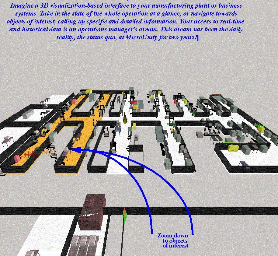
Tap the natural human ability to grasp and organize information spatially, and
watch the effective bandwidth and reliability of the link between your
organization and the computer take a quantum leap upward.
-
Dramatically simplify training procedures while reducing operator error and
frustration.
-
Video-conference between stations, so that operators, supervisors and
technical support can stay in touch throughout the day.
-
Ease customization through object-oriented design.
-
Simplify integration with other applications through the modular architecture.
-
Run complex database analyses through industry standard SQL.
Key Features
-
COMPLETE SYSTEM: 3D-Ops is a 3D-User Interface to a complete Operations
management system built on industry standard Sybase SQL database.
-
INCREASED INFORMATION BANDWIDTH: 3D-Ops increases the information
bandwidth between you and the computer by leveraging the power of visualization.
-
ZERO-RISK MIGRATION PATH: Take no risk in implementing 3D-Ops: No need to
discard existing software.
-
LINK DISPARATE DATA APPLICATIONS UNDER ONE FRONT-END: 3D-Ops acts as the
unifying front-end to your operations by linking external applications to
individual objects in the 3D model. This simple but powerful concept lowers
the access barriers between users and their data.
Just as a Relational Database Management System (RDBMS) ties together
disparate data elements into a cohesive whole, 3D-Ops ties together disparate
objects and related data and applications: 3D models, real-time operational
data, on-line notebooks, spread-sheets, web tools and graphs.
The Computer Communicates Visually with Us
Why 3D Visualization? What's Wrong with Menus and Command Lines?
3D-Ops leverages the power of human visual processing to present a rich
tapestry to the user. The state of the facility can be grasped in a single
glance, since the images combine their static appearance with features that
the computer generates in real-time. Visualizable databases are a big advance
over command lines and pull-down menus which communicate with machines via
single threads of thought.
Conceptual Space
3D visualization gives the computer the task of adapting to the user, rather
than forcing the user to adapt to the computer. The use of visualization taps
into our natural system of feature recognition and 3D spatial awareness. It
leverages that awareness to convey information and navigate among sources of
information. The computer translates its information into something that our
visual system and 3D awareness can absorb at higher speeds. In the same way
that a common language, or a lingua franca, is understood by all people, the
3D model is a common language understood by us and the computer.
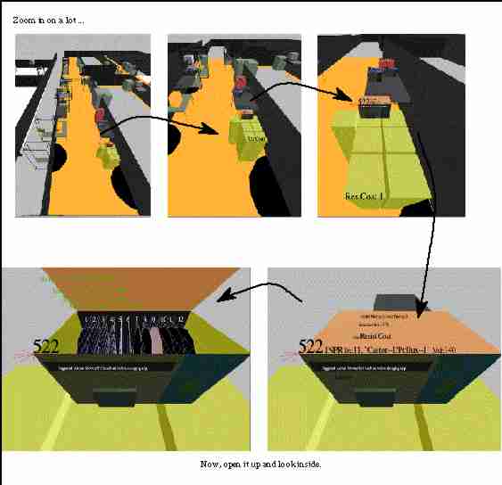
The visual simulation approach merges "conceptual space" with objects in 3D
space. First, objects related to each other are nearby, and a number of
different objects with their relatives are visible at a glance. For instance,
the simulation shows a product lot sitting on the machine that is physically
processing it. Information about that lot is accessed via "conceptual
objects," such as histories and pass-down logs, attached to the lot or the
machine. Second, the appearance of the objects, size, color, shape, relative
position etc., informs the viewer at a glance. For example, you can see the
lot's status, priority and type, the number of wafers inside and their status,
and how recently the lot and machine were touched.
By merging conceptual space with visual space, the database comes alive
BELOW: The picture below shows the state in one of MicroUnity's
photolithography manufacturing aisles. With this single screen, the user can
see that one machine is currently in process (indicated by yellow color), one
machine is ready for processing (indicated by grey color), one machine is down
(indicated by red color), there is high priority material present and it is
in-process (indicated by red star above the lot) and several standard lots are
waiting to be processed.
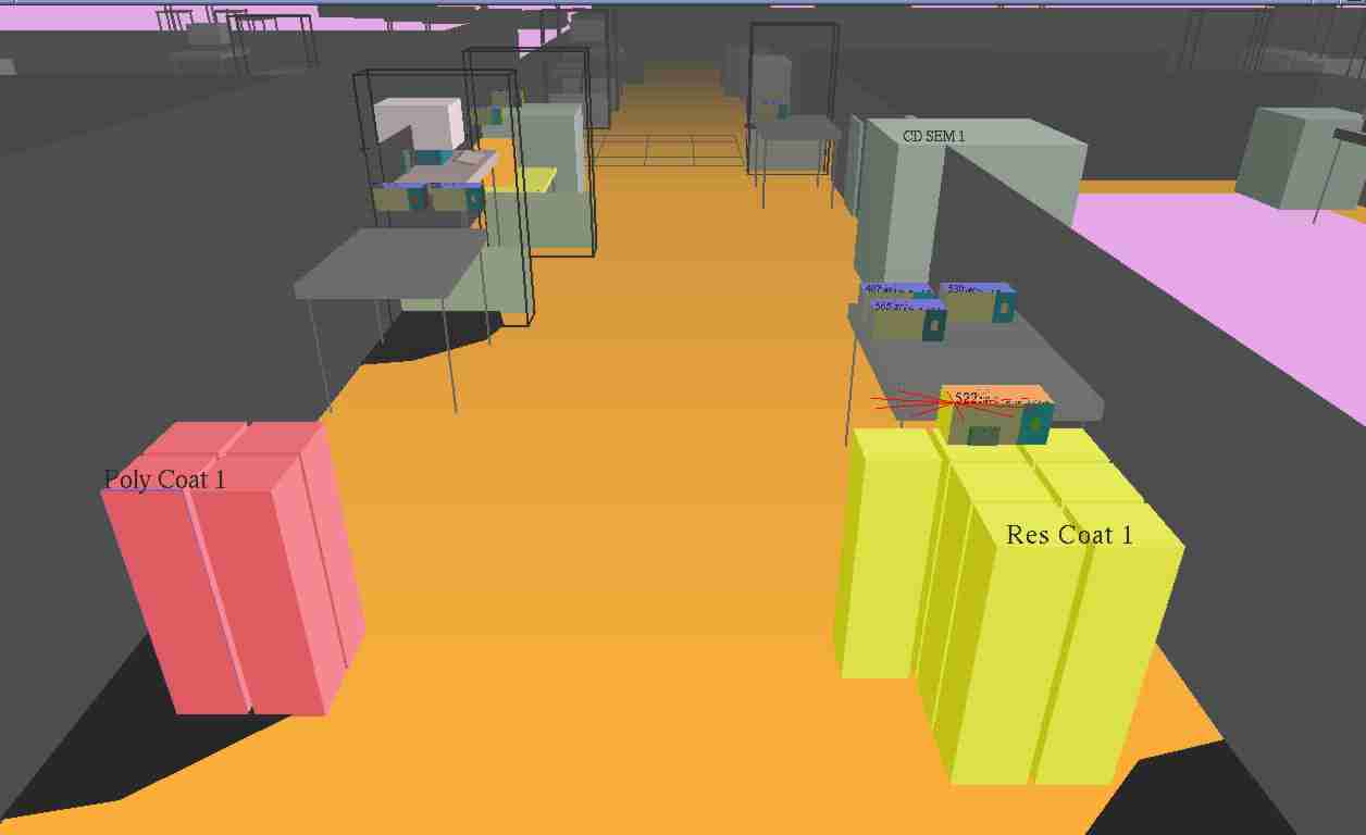
Your factory floor workers will be able to assess the condition of your
factory in less time than it took you to read this sentence. That is the power
of 3D-Ops. The human mind is capable of much higher bandwidth communication
than can possibly be provided by pull-down text mennfus, and 3D-Ops releases
that potential.
3D-Ops Components
3D Visual User Interface:
The user interface shows what is going on in the plant.
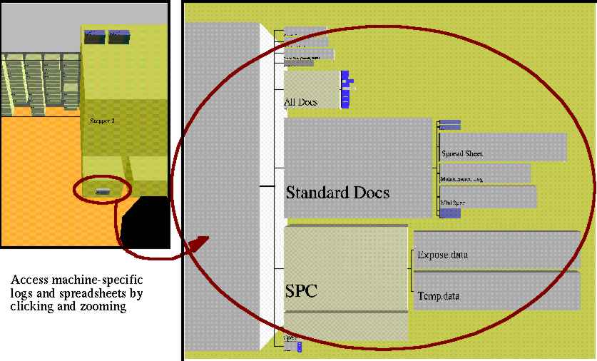
All of the objects on the screen come from the database; for instance
equipment, terminals, lots, aisles, etc. Objects can be added, deleted, moved
and resized from the user interface or directly in SQL. Information objects
can be attached to any physical object. For example, objects can be attached
to a process flow, a maintenance schedule, an image, a specification or a
logbook, etc. so that all items of information that are related to a physical
object in your factory can be accessed by clicking on the object in the user
interface. Even multi-media utilities can be launched from the user interface:
live video feeds from CIM (Computer Integrated Manufacturing) stations can be
launched by clicking on that object. Similarly, audio clips, bound to any
object, can be recorded by anyone and played at will.
Open SQL Database:
A Sybase SQL Server provides the underpinnings for the
operational state and business rules. A small number of function calls between
the 3D-Ops user interface and the database keeps them separable, and allows
changes to be made to one without complications with the other. This also
allows easy substitution of another database.
Support for Open Applications:
The open architecture connects to existing
business solutions such as inter/intra-net browsers and office application
suites. 3D-Ops' user interface takes previously stand-alone applications under
its wing, integrating them with the database in one location. Keep all your
existing software and simply use 3D-Ops as a front-end for your information technology.
Currently these applications are integrated into 3D-Ops:
- Web browser: an alternative text-based interface to the database. All
today's and tomorrow's web browser tools can be applied to the open SQL
database and accessed from any web-enabled computer. Inventory, Engineering
data, Machine-Down, current Work In Process and other reports can be accessed
real-time in a web browser from the database.
- Office applications: Applix notebooks are text files, tables and
spreadsheets which are launched from any of the objects in the 3D space using
the full power of this application suite.
Activities Supported by 3D-Ops
-
Shop Floor Control
-
Track work-in-process, view queues and generate real-time reports
-
Execute and track process split lots with multiple process flows
-
Keep your process flow documents virtual; use no paper
-
Append notes to individual steps for individual lots
-
View on-line specifications and maintenance procedures by navigating to the
object of interest
-
Maintenance and Engineering Management
-
Modify and view your equipment status and its history
-
Keep your pass-down logs, machine log books, statistical process control (SPC)
and test data on-line, associated with individual objects or entire regions of
your facility
-
Monitor automated equipment such as particle counters
-
Communications
-
Communicate by launching e-mail and paging utilities with a single keystroke
-
Record voice messages and attach them to objects for playback at any station
-
Write and read notebooks attached to any object in the facility
-
Utilize audible warnings and notices (safety conditions, scheduling delays or
conflicts, product quality monitors)
-
Broadcast information to all stations and hold video conferences between
multiple sites via integrated audio and video of each operator's terminal
Hardware Requirements and Scalability
The client-server system architecture allows you to completely separate the
user interface (on the clients) from the underlying Sybase database and
business logic (on the server). A simple set of functions connecting the user
interface and the underlying database, along with the use of standard SQL,
simplifies migration to different database vendors. The clients at MicroUnity
are entry-level Silicon Graphics workstations that send simple SQL messages to
the server. Scalability and the ability to expand the system as a whole rests
on the demands of the SQL server. The SQL server at MicroUnity is an SGI
Challenge 'S' (MIPS R5000 @180MHz, 64MB RAM) and even this entry-level machine
is significantly overpowered: the server load running 100 lots averaged less
than 5%. Sub-second response time is almost always seen for routine database
operations. This server leaves a great deal of room for client expansion, and
far larger capacity is possible by simply upgrading the server.
MicroUnity's package offers object code licensing and customizing support to
adapt this breakthrough technology for your site. For more information about
MicroUnity's 3D-Ops software system, or related technologies,
contact Rocky Nevin at:
CIM@MicroUnity.com (408) 734-8100
Copyright 1997 MicroUnity Systems Engineering, Inc. All rights reserved.
Any trademarks, service marks, product names or company names mentioned in
this document are the property of their respective owners.
The information in this document is provided in connection with MicroUnity
Software products. No License, expressed or implied to any intellectual
property rights is granted by this document. MicroUnity assumes no liability
whatsoever, and disclaims any expressed or implied warranty, relating to use,
including fitness for a particular purpose, merchantability, or infringement
of patent, copyright or intellectual property right.
The information in this document is subject to change without notice and
should not be construed as a commitment by MicroUnity Systems Engineering,
Inc. While MicroUnity wishes to assure the highest standards of accuracy, the
company cannot accept responsibility for inadvertent errors that may
nevertheless appear in this document. Questions and or suggestions regarding
the content of this document may be directed through the MicroUnity web site:
http://www.microunity.com/ .
Reproduction rights to this document are restricted to internal use and
reference use only.